|
Cisco CCNA
OSI Reference /
Network Protocols
|
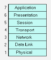
Application – The application layer
provides services directly to applications. The
functions of the application layer can include
identifying communication partners, determining
resource availability, and synchronizing
communication . Some examples of application layer
implementations include TCP/IP and OSI
applications such as Telnet, FTP, and SMTP, File
Transfer, Access, and Management (FTAM), Virtual
Terminal Protocol (VTP), and Common Management
Information Protocol (CMIP).
|
| |
|
Presentation
–The presentation layer provides a variety of coding and
conversion functions that are applied to application
layer data. These functions ensure that information sent
from the application layer of one system will be
readable by the application layer of another system.
Examples of presentation layer coding and conversion
schemes include ASCII, EBCDIC, JPEG, GIF, TIFF, MPEG,
QuickTime, various encryption methods, and other similar
coding formats.
|
|
Session –The
session layer establishes, manages, maintains, and
terminates communication sessions between applications.
Communication sessions consist of service requests and
service responses that occur between applications
located in different network devices. Some examples of
session layer implementations include Remote Procedure
Call (RPC), Zone Information Protocol (ZIP), and Session
Control Protocol (SCP).
|
|
Transport –
The transport layer segments and reassembles data into
data streams. It is also responsible for both reliable
and unreliable end-to-end data transmission. Transport
layer functions typically include flow control,
multiplexing, virtual circuit management, and error
checking and recovery. Some examples of transport layer
implementations include Transmission Control Protocol
(TCP), Name Binding Protocol (NBP), and OSI transport
protocols.
|
|
Network –The
network layer uses logical addressing to provide routing
and related functions that allow multiple data links to
be combined into an internetwork. The network layer
supports both connection-oriented and connectionless
service from higher-layer protocols. Network layer
protocols are typically routing protocols. However,
other types of protocols, such as the Internet Protocol
(IP), are implemented at the network layer as well.
Routers reside here at the network layer. Some common
routing protocols include Border Gateway Protocol (BGP),
Open Shortest Path First (OSPF), and Routing Information
Protocol (RIP). Packets and datagrams are sent across
this layer of the OSI model.
|
|
Data Link –
The data link layer provides reliable transmission of
data across a physical medium. The data link layer
specifies different network and protocol
characteristics, including physical addressing, network
topology, error notification, sequencing of frames, and
flow control. The Data link layer is composed of two
sublayers known as the Media Access Control (MAC) Layer
and the Logical Link Control (LLC) layer.
This can be
seen in the following diagram:
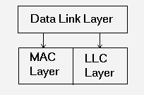
The LLC sublayer
manages communications between devices over a single
link of a network. LLC supports both connectionless and
connection-oriented services used by higher-layer
protocols. The MAC sublayer manages protocol access to
the physical network medium. The IEEE MAC specification
defines MAC addresses, which allow multiple devices to
uniquely identify one another at the data link layer.
Data link layer
implementations can be categorized as either LAN or WAN
specifications. The most common LAN data link layer
implementations include Ethernet/IEEE 802.3, Fast
Ethernet, FDDI, and Token Ring/IEEE 802.5. The most
common WAN data link layer implementations include Frame
Relay, Link Access Procedure, Balanced (LAPB),
Synchronous Data Link Control (SDLC), Point-to-Point
Protocol (PPP), and SMDS Interface Protocol (SIP).
|
|
Physical –
The physical layer defines the electrical, mechanical,
procedural, and functional specifications for
activating, maintaining, and deactivating the physical
link between communicating network systems.
Physical
layer specifications define such characteristics as
voltage levels, timing of voltage changes, physical data
rates, maximum transmission distances, and the physical
connectors to be used. Physical layer implementations
can be categorized as either LAN or WAN specifications.
Some common LAN physical layer implementations include
Ethernet/IEEE 802.3, Fast Ethernet, FDDI, and Token
Ring/IEEE 802.5.Some common WAN physical layer
implementations include High-Speed Serial Interface (HSSI), SMDS Interface Protocol (SIP), and X.21bis.
|
Steps of Data
Encapsulation
-
User information is
converted to data
-
Data
converted to
segments
-
Segments
converted to packets or datagrams
-
Packets
and
datagrams are converted to frames
-
Frames are
converted to bits
Data link addresses:
Physical address. Flat addressing scheme, physical address
burned into network card (MAC address)
Network address:
Logical address. IP or IPX – hierarchical scheme, assigned to
a machine manually or dynamically.
IP Address Classes
|
Class A
|
Net.Node.Node.Node |
0 |
1 – 127
|
127 networks, 16M
nodes |
|
Class B
|
Net.Net.Node.Node |
10 |
128 – 191
|
16K networks 65K
nodes |
|
Class C
|
Net.Net.Net.Node |
110 |
192-223
|
2M networks 254
nodes |
Subnetting Formulas
(count the bits only from the Node portion of the address.
Therefore, for a Class B address, the total masked bits +
unmasked bits = 16):
Max # of Subnets:
2(masked bits)-2
Max # of Hosts (per
subnet): 2(unmasked bits)-2
IPX
To turn on
ipx
routing
Then, on interface
ipx network {#}
encapsulation {sap, arpa, snap, hdlc, novell-ether}
{sec}
ipx network
3100 encapsulation sap sec
To monitor
sh ipx
traffic
sh ipx int
e0
Frame Types
802.3 – novell-ether –
default
802.2 – sap
Ethernet_II –
arpa
Ethernet_snap –
snap
LAN
Switching
All nodes on an ethernet
network can transmit at the same time, so the more nodes you
have the greater the possibility of collisions happening,
which can slow the network down.
LAN Segmentation:
breaking up the collision domains by decreasing the number of
workstations per segment.
FastEthernet (100bt)
– provides 10 times the bandwidth of older 10bastT Ethernet.
Must have Cat5 cable, no longer than 100 meters, and
FastEthernet NIC’s and Hubs/Switches
Full-Duplex Ethernet
– can provide double the bandwidth of traditional ethernet,
but requires a single workstation on a single switch port, and
NIC must support it. Collision free because there are separate
send and receive wires, and only one workstation is on the
segment. Half-Duplex must provide for collision detection,
therefore can only use 50% of bandwidth available
Bridges – examines
MAC address, and forwards frames unless the address was local.
Forwards to all other segments it is attached to. Forwards
multicast packets, so broadcast storms can occur.
Routers – examines
network address, and forwards using the best available route
to destination network. Can have multiple active
paths.
Switching – examines
MAC address. Same as multiport bridge.
Store-and-Forward –
copies entire frame into buffer, checks for CRC errors. Higher
latency. Used by Catalyst 5000 switches
Cut-Through – reads
only the destination address into buffer, and forwards
immediately. Low latency
Spanning-Tree
Protocol (STP) IEEE 802.1d. – developed to prevent routing
loops. STA (Spanning-Tree Algorithm) is implemented by STP to
calculate a loop-free network topology. In Catalyst 5000
network, BPDUs are send and received by all switches, and
processed to determine the spanning-tree topology.
Virtual LAN’s – have
different ports on a switch be parts of different subnetworks.
Some benefits: Simplify moves, adds, changes. Reduce
adminstrative costs, better control of broadcosts, tighten
security, distribute load. Relocate server into secured
locations.
IOS / Routing / Network
Security
User Mode – ordinary
tasks – checking status, etc. Need password depending on how
you’re entering (Virtual Terminal pw for telnet session,
Auxiliary pw for aux port, Console pw for console
port)
conf
t
line vty 0
{line aux 0} {line con 0}
login
password
letmein
Privileged
Mode
conf
t
enable
password letmein
Banner
conf
t
banner motd
#
Hostname
conf
t
hostname
MyRouter
Editing
CTRL+A – beginning of
line
CTRL+E – end of
line
show history
TAB completes
command
Help
Press ? after any command
for a list of what comes next
Router
Elements/Configuration
show
startup-config
show
running-config
copy
running-conifg startup-config
erase
startup-config
setup
reload
boot system {flash /
tftp}
copy flash tftp
copy tftp flash
copy run tftp
copy tftp run
show proc
show mem
show buff
show flash
show cdp
Routing
Protocols
Interior (within an
autonomous system – AS – group of routers under the same
administrative authority)
-
Distance Vector –
understand the direction and distance to any network
connection on the internetwork. Knows how many hops (the
metric) to get there. All routers w/in the internetwork
listen for messages from other routers, which are sent every
30 to 90 seconds. They pass their entire routing tables.
Possible problems: Slow convergance, Routing Loops,
Counting to Infinity (this is solved by maximum hop count)
Solutions: Split Horizon (cannot send information
back in the direction it was received) Hold-Downs (prevent
regular update messages from reinstating a route that’s gone
down)
RIP – 15 hop count
max
IGRP – 255 hop count
max, uses reliability factor (255 optimal), and
bandwidth
-
Link State –
Understands the entire network, and does not use secondhand
information. Routers exchange LSP’s (hello packets). Each
router builds a topographical view of the network, then uses
SPF (shortest path first) algorithm to determine the best
route. Changes in topology can be sent out immediately, so
convergance can be quicker
OSPF – decisions
based on cost of route (metric limit of 65,535)
EIGRP – hybrid
protocol, Cisco proprietary
Exterior
Manual
Routing
ip route {destination
network} {mask} {port, on remote side, to get
there}
ip route
172.16.10.0 255.255.255.0 172.16.40.1
Dynamic
Routing
router
rip
network
172.16.0.0
router igrp
{autonomous system #}
network
172.16.0.0
sh ip route
{rip / igrp}
Network Security / Access Lists
Standard IP access
list
access-list {number}
{permit / deny} {source address}
access-list
10 permit 172.16.30.2
Extended IP access list
access-list {number}
{permit / deny} {protocol} {source} {destination}
{port}
access-list
110 permit tcp host 172.16.50.2 host 172.16.10.2 eq
8080
Wildcard masks – use masks
to identify insignificant bits, eg
access-list 11 permit 172.16.30.0
0.0.0.255
(permits anybody with
172.16.30.x)
note: you can use 0.0.0.0
as the mask to limit to that specific host, or perfix it with
‘host’
Applying the list to an
interface (use access-group on the
interface)
int
e0
ip
access-group 110 out
IPX Access lists
Standard: access-list
{number} {permit/deny} {source} {destination}
Extended: access-list
{number} {permit/deny} {protocol} {source} {socket}
{destination} {socket}
access-list
810 permit 30 10
int
e0
ipx
access-group 810 out
IPX SAP Filters
access-list {number}
{permit/deny} {source} {service type}
To apply – on interface:
ixp input-sap-filter {number}
access-list
1010 permit 11.0000.0000.0001 0
int
e0
ipx
input-sap-filter 1010
Access list Numbers allowed
|
1-99 |
IP Standard
|
|
100-199
|
IP Extended
|
|
800-899
|
IPX Standard
|
|
900-999
|
IPX Extended
|
|
1000-1099
|
IPX SAP
|
To Monitor Access Lists
Show
access-list
WAN
Protocols
SDLC – developed by IBM in
70’s – Data link layer protocol that transports SNA over
WAN’s
HDLC – modified sdlc by
ISO, default on Cisco routers
X.25 – Sessions – DTE to
DTE communication
Full duplex, uses virtual
circuits (PVC and SVC)
Protocol Suite maps to
Physical through Network
PPP – runs on async
(dial-up) or sync (ISDN) lines. Supports multi-protocols.
Uses PAP or CHAP
authentication.
Int s0,
encapsulation PPP
Frame Relay – shared
bandwidth over public network. Virtual circuits are identified
by DLCI’s.
(Data Link Connection
identifiers). LMI, co-developed in 1990 by Cisco,
provides message information about current DLCI values (global
or local significance), and the status of virtual circutis.
Subinterfaces allow you to have multiple virtual
circutis on a single serial interface. You must map an
IP device to the DLCI (using the frame-relay map command or
the inverse-arp function)
int
s0
encapsulation
frame-relay {ietf}
note: if you don’s
specify ietf, it uses cisco by default
frame-relay
interface-dlci {#}
frame-relay
lmi-type {cisco, ansi, q933a}
Subinterfaces
int s0.x
{multipoint / point-to-point}
Mapping
int
s0
inverse-arp
or
frame-relay
map ip x.x.x.x #
Monitoring
show frame
{pvc / ip / lmi / traffic / etc.}
ISDN - digital service that
runs over existing telephone networks
Normally used to support
applications requiring high-speed voice, video, and data
communications for home users, remote offices, etc.
ISDN Terminal equipment
types
TE1 – understand ISDN
standards
TE2 – predate ISDN
standards, require a TA (terminal adaptor)
Reference Points
describe the point between
R – non-ISDN and
TA
S – user terminals and
NT2
T – NT1 and NT2
devices
U – NT1 and line
termination
ISDN
Protocols
E – on existing telephone
network
I – concepts, terminology,
and services
Q – switching and
signaling
ISDN
BRI: 2 64K B channels,
plus 1 16K D channel
ISDN
PRI
23 64K B
channels, plus 1 64K D channel (North America &
Japan)
30 64K B channels, plus 1 64K D channel (Europe
& Australia)
Configuration
example
config
t
isdn
switch-type basic-dms100
int
bri0
encap
ppp
isdn spid1
775154572
isdn spid2
455145664
|

