|
Cisco CCNA Wan
Switching
ATM Basics
ATM is a packet-switched
technology based on a 53-byte packet called a cell. Each cell is divided
into a 5-byte header and a 48-byte payload. The short, fixed length cell
reduces delay and jitter, allowing time sensitive information such as
voice and video to be transported along with data. There are various
transmission media and rates available with bandwidth measured in megabits
to gigabits.
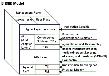
ATM Model
ATM is based on Broadband
Integrated Services Digital Network, an extension of ISDN. Similar to the
OSI model, B-ISDN uses a seven-layer model. ATM redefines the lower 3
layers into the Physical Layer, the ATM Layer and the ATM Adaptation
Layer.
ATM Headers
The ATM Cell has a 5-byte
header, with the remaining 48-bytes left for payload (data).

There are two standard
headers. Cisco added an additional header type to allow for advanced ATM
features.
-
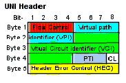
User-to-Network Interface (UNI)
header-specifies the interface between a user device and a network.
Note: A user device is not just a computer interface. It can be a
router or switch as well.
-
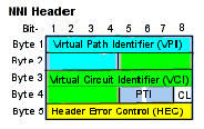
Network-to-Network Interface (NNI)
header-specifies interface between two networks. Usually a private ATM
network and a public ATM network.
-
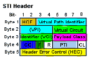
STI header-used between two Cisco
ATM switching nodes to allow advanced network features.
-
Flow Control (4-bits)-a UNI field
for controlling access and flow control. Usually all zeros, as there is
no defined standards.
-
Virtual Path Indicator (VPI)-identifies the path to be taken by the ATM cell.
-
Virtual Circuit Indicator (VCI)-indicates the circuit number on the path.
-
Payload Type Indicator (PTI,
3-bits)-the type of data being carried in the payload. High order bit is
0 for user data and 1 for connection management information, second bit
indicates if there was congestion, and the third bit shows if user data
is from customer premises equipment.
-
Payload Class (4-bits)-STI field
indicating classes of service and BPX switch queues.
-
Cell Loss Priority bit
(CL)-indicates that the cell may be discarded if congestion is
encountered.
ATM Addressing
-
VCI identifies the circuit or
connection.
-
VPI identifies the virtual path.
-
The path can be seen as a trunk that
carries multiple circuits between switches.
-
VCI is 16-bits allowing 65, 535
circuit numbers. For the STI header VCI is 8-bits for 256 circuits.
-
VPI is 8-bits for the UNI header,
12-bits for the NNI header (4096 paths), and 10-bits for the STI header
(1024 paths).
Cisco ATM Addressing
|
|
|
|
|
BAM-BPX switch
Addressing Mode |
|
|
IPX switch to BPX
switch, or between IPX nodes |
CAM-Cloud
Addressing Mode |
|
User defined VPI
Node derived VCI |
Between IPX or IGX
nodes and on networks switched on VPI only |
SAM-Simple
Addressing Node |
|
|
Between IPX or IGX
nodes and on networks where routing is user
programmed |
ATM Adaptation Layer
|
|
|
|
|
|
|
|
|
|
|
|
|
|
|
|
|
|
|
|
|
|
|
|
|
|
|
|
|
|
|
|
Uncompressed
voice, Constant bit-rate video |
Compressed Voice
and Video |
Frame-relay, SNA,
TCP/IP, e-mail |
|
Quality of Service
These are some of the most
important QoS parameters:
-
Peak Cell Rate (PCR)-maximum rate a
sender can send cells.
-
Sustained Cell Rate (SCR)-required
cell rate averaged over a long interval.
-
Minimum Cell Rate (MCR)-minimum
acceptable rate of cells per second.
-
Cell Loss Ratio (CLR)-the fraction
of cells not delivered or delivered late.
-
Cell Transfer Delay (CTD)-time from
source to destination (transmit time).
-
Cell Error Ratio (CER)-fraction of
cells delivered with incorrect bits.
-
Cell Delay Variation (CDV or
Jitter)-how regularly cells are delivered. Cells from one conversation
on a multiplexed connection may be delayed while cells from another
conversation are delivered.
-
Cell Delay Variation Tolerance (CDVT)-amount of variation in cell transmission times. Specified
separately for PCR and SCR.
Service Categories
The ATM Forum specifies four
service categories:
-
Constant Bit Rate (CBR)-entire
connection, from source to destination, including intermediary switches,
provides a set amount of bandwidth at all times. Expensive because
bandwidth is reserved even if it is not used.
-
Variable Bit Rate (VBR)- guarantees
an average bit rate over time, but allows a higher peak bit rate, with
no cells lost, for a certain amount of time each minute. VBR is broken
into two subclasses real time (rt) and non-real time (nrt).
-
rt-VBR is used for connections
that require end-to-end timing, such as voice or video connections
using compression or noise reduction.
-
nrt-VBR can be used when timing
relationships are not required, but QoS is still needed.
-
Available Bit Rate (ABR)-bit rate
varies according to network conditions up to a stated maximum. Source
adjusts transmission rate due to network information received from the
network.
-
Unspecified Bit Rate (UBR)-no set
bit rate guarantee. Allows a transmission rate up to a certain maximum,
with no guarantee of cell loss or delivery.
Frame Relay Basics
Frame relay
-
Defines a connection between user
equipment and a WAN, not the interface or protocols of the WAN itself.
Usually describes a LAN-to-LAN connection.
-
A standard optimized for the
transport of protocol-oriented data.
-
Defines network paths using
statistical multiplexing (creates virtual circuits).
-
Does not allocate bandwidth until
data needs to be transmitted.
-
Combines packet switching and port
sharing with time division multiplexing circuit switching to allow
multiple point-to-point permanent virtual circuits over a single
physical interface.
-
Operates only on the Data Link and
Physical layers of the OSI model. Routing is general handled by the
Network layer protocol.
Components of Frame Relay
-
Committed Information Rate
(CIR)-rate of data transfer under normal operations. Generally the
contracted rate from the public service provider. CIR should never be
set higher than the speed of the slowest physical connection on a VC.
CIR of 0=best effort.
-
User-Network Interface (UNI)-describes a connection between user equipment and a frame relay
network. Usually, a router (DTE) and the service provider.
-
Network-Network Interface-describes
connection between frame relay networks.
-
Local Management Interface (LMI)-monitors the status of DLCIs by periodically polling the network.
Can be used to exchange status information between frame devices and the
network. Also supports multicasting, global addressing and flow control.
Cisco switches support LMI.
-
Bandwidth on Demand-capacity is
provided as a PVC requires it up to the maximum CIR.

-
Flag-first and last byte of a frame,
indicating the beginning and the end. There may be only one flag between
frames with the end flag of one frame used as the start flag of the
next.
-
Data Link Connection Identifier (DLCI)-10-bit routing address of the PVC at a particular UNI or
NNI.
Some DLCIs are reserve for signaling, management and future use so only
16 to 1007 are used to address virtual circuits.
-
Command/Response (C/R)-not used.
Always set to 0.
-
Extended Address (EA)-allows the
header to be lengthened to 3 or 4 bytes enabling a DLCI longer than
10-bits (more VC addresses).
-
Forward Explicit Congestion
Notification (FECN)-set to 1 by the frame network when congestion is
occurring on the packet forwarding direction of the frame.
-
Backward Explicit Congestion
Notification (BECN)- set to 1 by the frame network when congestion is
occurring on the reversed packet forwarding direction of the frame.
-
Discard Eligibility (DE)-set by the
end node to indicate frames to be discarded if congestion occurs.
-
Data-also called the information
field. May be as large as 4,520 bytes, but is more efficient with a size
of less than 4K.
-
Frame Check Sequence (FCS)-standard
cyclic redundancy check that detects bit errors in the frame.
General Installation
Tools Required
Installation Outline
Preliminary Steps
-
Prepare the site for equipment
installation
-
Location should have restricted
access.
-
Sufficient area should be
available to access the equipment.
-
The proper power requirements need
to be met.
-
Confirm that the UPS meets Cisco
requirements
-
Airflow and cooling must be
suitable for the equipment being installed.
-
Verify that all parts ordered are
present and in good condition. Record all part numbers and serial
numbers.
-
Unpack and install the equipment in
the desired rack (may be provided by Cisco or third party). Follow the
instructions in the supplied install guide.
-
Install and connect the required
power supply. Most models are available in either AC or DC versions.
-
Install the cards in the equipment.
Most cards consist of a front and back card pair. If cards are not
matched, alarm conditions will occur. All Cisco WAN switches have
specific slots reserved for certain cards. These reservations must be
followed. Proper grounding (wrist strap) must be followed prior to
handling any cards.
-
Install the cable management system
and connect the cables to the required ports.
-
Connect a management terminal or
Cisco WAN Manager workstation to the console port.
Installation troubleshooting
If there is no power to the
switch
-
Check the power cables.
-
Check the circuit breaker.
-
Check for card short circuit (pull
and reseat all cards).
-
Check power supply fault.
No LED lit on a single card
-
Remove and reseat card.
-
Check card fuse if applicable.
-
Replace card. If replacement does
not fix problem, check the backplane.
Alarm Indicator on Card
Command Line Interface (CLI)
Connect to an IGX or BPX
with a PC using a terminal emulator (hyperterm), or a terminal connected
via the control port, a LAN connection, or remotely using a modem
connected to the auxiliary port.
-
Once connected, hit enter to bring
up the command screen.
-
Enter user name at the logon prompt
-
Enter password at the password
prompt.
-
The bye command ends the
session.
Use vt <nodename> to
create a virtual terminal session on a remote node .
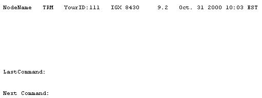
Command Screen Format
-
Top line displays node name, current
user, software revision, date, time and time zone.
-
The middle of the screen shows
information returned by executed commands.
-
The bottom of the screen displays
prompt for current command or next command.
Basic commands
-
. (period) -displays the last twelve
commands. Enter a command number to re-use a command.
-
help or ? –displays a help menu. If
typed with a command brings up help for that command.
-
bye –ends local or remote session.
-
clrscrn
–clears the display.
-
prtscrn
–sends current display to printer.
-
redscrn
–redraws display (useful if connected via
modem).
-
vt –used to start virtual terminal session with remote
nodes.
Numbering Conventions
Trunks, Lines and Channel Numbers
|
|
|
|
CDP/CVM Circuit Line
and
NTC/NTM
Trunk |
|
Slot number of the
BC-T1 or BC-E1 (primary if redundant pair) back card connected to
IGX. |
|
|
|
Slot number of the
BC-T3 or BC-E3 back card. |
|
|
|
Slot number and port
of the BNI that has the T3 cable attached. |
|
|
slot.ch-ch (sets of
channels) |
Back slot number of
the circuit line and channel or range of
channels. |
|
|
|
Back slot number of
the data card and the port number or range of ports on that
card. |
Frame Relay channel
numbers (local addressing) |
|
Back slot number of
FRP card and the port number of the connection. DLCI only has local
significance to the port. |
Frame Relay channel
numbers (global addressing) |
|
Back slot number of
FRP card and the port number of the connection. DLCI is unique to
port for entire network. |
Viewing Node Configuration
Display commands are also
useful for troubleshooting.
-
Display cards in shelf-dspcds.
-
Display status, serial number and
revision of a card-dspcd.
-
Display redundant cards (y-pairs)-dspcdred.
-
Display LAN port
configuration-dsplancnf.
-
Display power supply status and
cabinet temperature-dsppwr.
-
Display control port and auxiliary
port configuration-dsptermcnf.
-
Display function of control port and
auxiliary port-dsptermfunc.
Privilege Levels
-
There is one super user privilege
level (level 0), and six user levels (levels 1 through 6).
-
Each privilege level has access to
commands of the lower levels (level 4 can access commands for levels
4-6).
Managing Users
-
Add users use the adduser command. (You can only create a user for a
lower privilege level than you are logged in as.)
-
Change password use cnfpwd.
-
Remove users with deluser.
Management Workstation
On the Switch
-
Set up the LAN port with cnflan.
-
Configure the SNMP get and set (read
and write) community names with cnfsnmp.
-
Configure the IP for the statistics
manager, if you are using Cisco WAN Manager Statistics Collection
Manager, using cnfstatmast (cnfstatmgr on the MGX switches).
Alarms
-
Use dspnw to show a list of network nodes and trunk alarm
status.
-
Use dspnds to list name, type and alarm status of nodes on
the network.
-
dspalms
displays a summary of all alarms on the
current node.
-
dsplogs to view log of errors.
Redundancy
-
Set up card redundancy-addyred (or addcdred).
-
Switch between active and redundant
cards-resetcd.
-
Switch between active and standby
processor-switchcc.
BPX 8600 Series
The BPX 8600 series switches
are high capacity, standards based broadband ATM switches that support:
Card Types
Installing BPX Cards
-
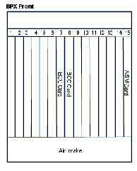
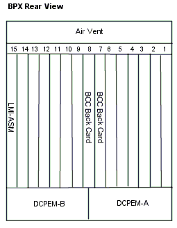
When installing cards, follow ESD
precautions.
-
Slot 7 is reserved for BCC card.
Redundant nodes have a BCC card in slots 7 and 8.
-
Slot 15 is for the ASM/LM-ASM card
pair.
-
Slots 1-6 and 10-15 are for all
interface cards.
19.2 Gbps Operation
The BPX switches support a
9.6 or a 19.2 Gbps backplane. For 19.2 Gbps support, you need:
-
19.2 Gbps backplane identified by
white slot fuses on bottom rear of backplane (or result of “Word
#2=0001” from dspbpnv command).
-
Backplane NOVRAM that indicates the
backplane is 19.2 Gbps capable
-
BCC-4 or later controller.
-
Switch software release 8.1.18 or
later.
-
At least one BXM card.
|
Table of BPX Cards |
|
|
|
|
|
|
|
|
|
|
Broadband controller
card, can be installed in redundant pairs. Uses System Software ver
7.0 and above. |
|
|
|
|
|
|
|
Broadband controller
card, can be installed in redundant pairs. Uses System Software ver
7.X (7.2.84 and above) or 8.X (8.1.12 and above). |
|
|
|
Enhanced BCC-3. Can
support VSI or MPLS. |
|
|
|
Broadband controller
card, can be installed in redundant pairs. Uses System Software 8.4
or above, has 64+ MB or RAM and supports 19.2 Gbps BXM card
operation. Can support VSI or MPLS. |
|
|
|
Back card used with
BCC-3 or BCC-4 (also called LM-BCC). |
|
|
|
Alarm/Status Monitor (ASM) Card. |
|
|
|
|
|
|
|
|
|
|
|
8 or 12 port E3/T3
card. Used in either network interface or service access (UNI) mode,
with T3 or E3 interface. |
|
|
|
Back card for
BXM-T3/E3-8 or BXM-T3/E3-12. |
|
|
|
4 or 8 port
OC-3/STM-1 card. Used in either network interface or service access
(UNI) mode. |
|
|
|
Back cards for
BXM-155-4 for different fiber modes. Multi-mode fiber, single mode
fiber and single mode, long range fiber
respectively. |
|
|
|
Back cards for
BXM-155-8 for different fiber modes. Multi-mode fiber, single mode
fiber and single mode, long range fiber
respectively. |
|
|
|
1 or 2 OC-12/STM 4
ports. Used in either network interface or service access (UNI)
mode. |
|
|
|
Used with SMF-622-2
back card for multicast connections. Port 1 loops to port 2, tx to
rx and rx to tx (cross-over). |
|
|
|
Back cards for
BXM-622. Single mode fiber, single mode, long range fiber and extra
long-range fiber respectively. XLR supports 1500mm
interface. |
|
|
|
Back cards for
BXM-622-2 and BME. Single mode fiber, single mode, long range fiber
and extra long-range fiber respectively. |
|
|
|
Broadband NIC with 3
T3 ports. |
|
|
|
Line module for
BNI-T3 for 3 physical T3 ports. |
|
|
|
Broadband NIC with 2
OC-3/STM-1 ports. |
|
|
|
OC-3/STM-1 interface
card for BNI-155 or ASI-155 front card. Multi-mode fiber, single
mode fiber and single mode, long range fiber
respectively. |
|
|
|
|
|
|
|
ATM Service
Interface Card with 2 T3 ports. |
|
|
|
Line module with 2
physical T3 ports for use with ASI-1-2T3. |
|
|
|
ATM Service
Interface Card with 2 E3 ports. |
|
|
|
Line module with 2
physical E3 ports for use with ASI-1-2E3. |
|
|
|
ATM Service
Interface Card with 2 OC-3/STM-1 ports. |
|
|
|
OC-3/STM-1 interface
card for BNI-155 or ASI-155 front card. Multi-mode fiber, single
mode fiber and single mode, long range fiber
respectively. |
|
|
|
|
|
|
|
|
|
|
|
Optional AC Power
Supply. |
|
Initial Configuration
-
Set up the node
-
Set node name with cnfname
command.
-
Time zone-cnftmzn.
-
Date-cnfdate.
-
Time-cnftime.
-
LAN interface-cnflan.
-
Configure console or aux ports to
support any external devices using cnfprt (configure printing), cnfterm (configure tx parameters), and conftermfunc (configure port functions).
-
Set up the trunks (use dspcds to ensure proper cards are installed)
-
Up trunk at each node-uptrk.
-
Configure trunk parameters-cnftrk.
-
Add trunks at each node-addtrk.
-
Configure redundancy (if
require)-addyred.
-
Configure IGX interface shelf (if
present).
-
Set up trunk between BPX and IGX
as above.
-
Contact Cisco customer service to
add options.
-
Add IGX as shelf at BPX-addshelf.
-
Add MGX 8220 Shelf (if present).
-
Add MGX as a shelf at BPX-addshelf.
-
Set up ATM services.
-
Activate line-upln.
-
Configure line-cnfln.
-
Activate ports-upport.
-
Configure ports-cnfport.
-
Configure ATM connections.
-
Add connection-addcon.
-
Configure connection type-cnfcontyp.
-
Set up ATM to Frame Relay (ATF).
-
Add connection-addcon.
-
Specify connection class-cnfcls.
-
Add connection group-addcongrp.
-
Configure Interface Shelf to Frame
Relay Connections.
-
Connections are added using Cisco
WAN manager.
-
Frame Relay connections from IGX
to BPX.
-
ATM or Frame Relay connections
from MGX to BPX.
-
Connections are end-to-end and
managed via SNMP.
IGX 8400 Series
Card Installation
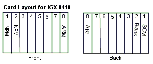
-
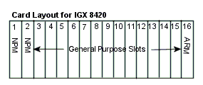
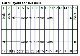
Remove jumper W6 on the system
clock module (SCM) card(s) to indicate an IGX 8430. The jumper is left
on for 8420s.
-
A maximum of 16 trunk cards can be
used on the 8430.
Non-redundant configurations
always have the NPM card in slot 1. Redundant configurations have NPMs in
slots 1 and 2. The SCM card always goes behind the NPM in slot 1.
The ARM card can go in any
slot, but is usually installed in the far right.
Table of IGX Cards
|
|
|
|
|
|
|
|
|
|
|
|
|
|
|
|
32 MB Controller
Card Rev B. |
|
|
|
64 MB Controller
Card Rev B. |
|
|
|
|
|
|
|
|
|
Alarm Relay
Interface, back card for ARM. |
|
|
|
System Clock Module,
works with NPM. |
|
|
|
|
|
Universal Switching
Module. |
|
|
|
OC3/STM1, 2 or 4
port multimode or single mode fiber back card. |
|
|
|
3 or 6 port T3 back
card with BNC connectors. |
|
|
|
3 or 6 port E3 back
card with BNC connectors. |
|
|
|
4 or 8 port T1 Back
card with DB 15 connectors. |
|
|
|
4 or 8 port E1 back
card with DB15 connectors. |
|
|
|
4 or 8 port E1 back
card with BNC connectors. |
|
|
|
ATM Line Module,
model B. |
|
|
|
Universal ATM
interface. Single T3 interface with BNC connectors. |
|
|
|
Universal ATM
interface. Single E3 interface with BNC connectors. |
|
|
|
|
|
|
|
Single E3 interface
with BNC connectors (maximum throughput 16Mbps) |
|
|
|
Single E2 interface
(8.44 Mbps) with BNC connectors. Only operates between Cisco Wan
switches so UNI not supported. |
|
|
|
Single 50-pin HSSI
connector for aggregate T1. Requires external DSU. |
|
|
|
Single T3 interface
with BNC connectors (maximum throughput 16Mbps) |
|
|
|
Single E1 trunk
interface with both DB15 and BNC connectors. |
|
|
|
|
|
|
|
Single E1 trunk port
with both DB15 and BNC connectors. |
|
|
|
Single T1 trunk port
with DB 15 connector. |
|
|
|
Single Japanese Y1
interface (1.54 Mbps) with DB15 and Y1 trunk i/o
connectors. |
|
|
|
Single J1 interface
back card. |
|
|
|
Subrate back card
for partial E1 or T1 bandwidth. V.11/X.21, V.35 and EIA/TIA-449
interface. |
|
|
|
|
|
|
|
Universal
Transmission Module. Same card as above-uses the same back
cards. |
|
|
|
ATM Line Module,
Model A. Uses same back cards as ATM/B above. |
|
|
|
|
|
|
|
|
|
|
|
|
|
|
|
|
|
|
|
|
|
Channelized Voice
Module, ADPCM, T1 and E1. |
|
|
|
T1 interface with
DB15 connector. |
|
|
|
E1 interface with
DB15 and alternate BNC connectors. |
|
|
|
J1 interface with
DB15 and alternate BNC connectors. |
|
|
|
|
|
Channelized
Universal Frame Module, supports 4 ports. |
|
|
|
Channelized
Universal Frame Module, supports 8 ports. |
|
|
|
8 port T1 interface
card for UFM-4C or UFM-8C (only 4 ports recognized for UFM-4C), with
DB 15 connectors. |
|
|
|
8 port E1 interface
card for UFM-4C or UFM-8C (only 4 ports recognized for UFM-4C), with
DB 15 connectors. |
|
|
|
8 port E1 interface
card for UFM-4C or UFM-8C (only 4 ports recognized for UFM-4C), with
BNC connectors. |
|
|
|
Unchannelized
Universal Frame Module for HSSI, V.35 and X.21. |
|
|
|
|
|
|
|
|
|
|
|
|
|
|
|
Unchannelized Frame
Module for V.35/X.21. |
|
|
|
4 port V.35
interface. Model A supports 1024 Mbps, model B supports 2048
Mbps. |
|
|
|
|
|
|
|
Unchannelized Frame
module, Port Concentrator only. |
|
|
|
Provides connection
to port concentrator supplying up to 44 X.21 ports (ports appear as
logical ports to the IGX) |
|
|
|
|
|
|
|
Single T1 port with
DB15 connector. |
|
|
|
Single E1 port with
DB15 and alternate BNC connectors. |
|
|
|
|
|
|
|
|
|
4 port RS232c v.24
synchronous data interface. |
|
|
|
4 port RS232d v.24
synchronous data interface. |
|
|
|
4 port RS449 x.
synchronous data interface. |
|
|
|
4 port v.35
synchronous data interface. |
|
|
|
|
|
|
|
4 or 8 port RS232c
v.24 low-speed data interface. Up to 56 kbps for 4 ports and 19.2
kbps for 8 ports. |
|
|
|
4 or 8 port RS232d
v.24 low-speed data interface. Up to 19.2 kbps. |
|
|
|
|
|
Frame trunk module.
Provides a connection to Fastpad devices or other Cisco access
products. |
|
|
|
4 port V.35 or X.21
interface card. Each port supports one Fastpad
connection. |
|
|
|
DB15 and alternate
BNC Fastpad connection card. |
|
Initial Configuration
-
Set up the node.
-
Set node name with cnfname
command.
-
Time zone-cnftmzn.
-
LAN interface-cnflan.
-
Configure console or aux ports to
support any external devices using cnfprt (configure printing), cnfterm (configure tx parameters), and conftermfunc (configure port functions).
-
Set up the trunks (use dspcds to
ensure proper cards are installed).
-
Up trunk at each node-uptrk.
-
Configure trunk parameters-cnftrk.
-
Specify Cellbus bandwidth as
needed for UXM-cfbusbw (super-user command).
-
Set up optional y-cable
redundancy-addyred.
-
Configure trunk redundancy-addtrkred.
-
Add desired subrate trunk
interface control templates-cnftrkict.
-
Set up voice lines.
-
Activate line-upcln or upln.
-
Configure line-cnfln.
-
Configure redundancy-addyred.
-
Set up data lines and ports.
-
Activate line-upcln.
-
Configure line-cnfln.
-
Configure redundancy-addyred.
-
Set up Frame Relay lines and ports.
-
Activate ports-upfrport.
-
If UFM-U card, specify the mode-cnfmode (use dspmode to display current mode).
-
Set up FastPAD lines and ports.
-
Activate line-upln.
-
Activate ports-upftcport.
-
Add FastPAD control connection-addfp.
-
Set up ATM lines and ports.
-
Activate line-upln.
-
Configure line-cnfln.
-
Add ports-upport.
-
Configure ports-cnfport.
-
Configure Cellbus bandwidth for
uxm-cnfbusbw.
-
Configure Voice connections
-
Add connections-addcon.
-
Configure parameters.
-
Additional configuration
parameters for UVM.
-
Configure data connections.
-
Add connection-addcon.
-
Configure parameters.
-
Configure data channel clock-cnfdclk.
-
Configure control lead
direction-cnfcldir.
-
Set interface control template
signals-cnfict.
-
Configure Frame Relay connections.
-
Add connection-addcon.
-
Configure connection classes-cnfcls.
-
Configure parameters.
-
Control templates-cnfict.
-
Channel utilization-cnfchutl.
-
Channel priorities-cnfchpri.
-
Configure connections to access
device (such as Cisco 3800).
-
Up port to access device-upftcport.
-
Add device to node-addad (view
connected access devices with dspads).
-
Add connection at FTC/FTM-addcon (if other end is CDP or CVM connection is
added there).
-
Configure Congestion Management
Timer-cnfadcmtmr (optional).
-
Configure FastPAD connections.
-
Add connection-addcon.
-
Configure for permanent or
switched voice connections.
-
Configure ATM connections.
-
Add connection-addcon.
-
Set connection type-cnfcontyp.
-
Optimize routing and bandwidth.
-
Optimize channel utilization-cnfchutl.
-
Specify preferred route-cnfpref.
-
Set Class of Service (CoS)-cnfcos.
MGX Series Installation
MGX 8220

-
MGX 8220 can also be used stand-alone
to interface with third-party ATM devices.

Card Installation
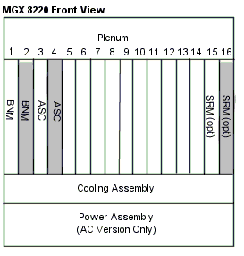
-
Installation of the SRM is optional,
but must conform to the installed BNM and ASC cards (slot 15 if slots 1
and 3 used and slot 16 if slots 2 and 4 are used-both slots 15 and 16
for redundant configuration).
MGX 8220 Interface Cards
|
|
|
|
|
|
|
|
Axis Shelf
controller, enhanced version. Back card has Control ports and LAN
port. |
|
|
|
|
|
|
|
Broadband Network
Module with one SONET/SDH port. |
|
|
|
Single Mode Fiber
interface back card for AX-BNM-155. |
|
|
|
|
|
|
|
Back cards for above
with either DB15 or BNC interface connectors. |
|
|
|
T1E1 Service
Resource Module. Supports BERT and 1 to N redundancy for Service
Modules. |
|
|
|
SRM supports bulk
mode redundancy support for up to 84 T1 channels. |
|
|
|
Back card for
AX-SRM-3T3 with 3 BNC connectors. |
|
|
|
|
|
Circuit Emulation
Service Module supporting 8 T1 or E1 connections. |
|
|
|
ATM UNI Service
Module supporting 8 T1 or E1 connections. |
|
|
|
|
|
|
|
High speed Frame
Service Module. Supports 4 port X.21 or V.35 connections or 2 HSSI
connections with the appropriate back card. Up to 10 Mbps per
port. |
|
|
|
High speed Frame
Service Module, B version. Supports 4 port X.21 or V.35 connections
or 2 HSSI connections with the appropriate back card. Up to 10 Mbps
per port. |
|
|
|
Very high speed
Frame Service Module. Supports 2 HSSI ports at up to 52 Mbps per
port. |
|
|
|
Frame Service Module
supporting 8 T1 or E1 connections. |
|
|
|
Frame Service Module
supporting 8 channelized T1 or E1 connections. |
|
|
|
T1 or E1 Service
Module back card with 8 RJ48 connectors. |
|
|
|
Redundancy back card
for AX-RJ48-8T1. |
|
|
|
Service module back
card with 8 miniature SMB connectors, supporting E1
clocking. |
|
|
|
Redundancy card for
above. |
|
|
|
4 port X.21 back
card with DB15 connectors. |
|
|
|
4 port V.35 back
card with DB15 connectors. |
|
|
|
2 port HSSI back
card with SCSI2 connectors. |
|
|
|
2 port HSSI back
card with SCSI2 connectors. B version. |
|
|
|
Inverse Multiplexer
for ATM Trunk Module supports 8 T1 or E1 connections. B version.
Makes it possible to use up to 8 T1 or E1 connections as a trunk
instead of a T3 or E3. |
|
|
|
1 T3/E3 port with
BNC connector and 8 T1/E1 port with RJ48 connectors back card for
IMATM. |
|
|
|
1 E3 port and 8 E1
port back card for IMATM with miniature SMB
connectors. |
|
Initial Configuration
-
Connect a terminal or PC using
terminal emulation software to the maintenance port of the active ASC
card.
-
Hit return to get a login prompt.
-
Login using user name, password and
number of active ASC card.
-
Use cnfifip command to configure control, LAN and in-band
ports.
-
Use cnfname CLI command to configure the shelf nodename.
-
Logout.
You can now configure connections
and manage the node using Cisco Wan manager (or the CLI).
MGX 8850
MGX 8850 is an IP+ATM switch that
can be used as a stand-alone device or as a feeder to a BPX 8600 series
switch.
A feeder of narrow-band and
medium-band ATM, Frame Relay and voice into a single, wide-band ATM
feeder trunk to the BPX.


Card Installation
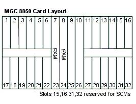
The MGX 8850 has a 32 slot,
dual plane architecture. To accommodate double height cards, 4 single
height slots can be converted into 2 double height slots.
-
Slots 7 and 8 are reserved for the PXMs.
-
If SCMs are used, the PXM in slot 7
controls the SCM in slots 15 and 31. The PXM in slot 8 controls slots 16
and 32.
-
If RPM cards are used, slots 9 and
10 should be used due to backplane wiring.
Single to Dual Height Slot Conversions
-
Begin at the left and move to the
right. Starting points can be slots 1 and 2 (with 17 and 18), or 9 and
10. SRM slots 15 and 16 can be converted out of sequence.
-
After conversion the slot takes the
number of the top single height slot.
MGX 8850 Interface Cards
|
|
|
|
|
|
|
|
Double height
Processor Switch Module for 1.2 Gbps switch fabric. |
|
|
|
Double height
Processor Switch Module for 45 Gbps crosspoint switching
fabric. |
|
|
|
PXM-1 with support
for 2 T3 or E3 lines. |
|
|
|
PXM-1 with support
for 4 OC3/STM1 lines. |
|
|
|
PXM-1 with support
for a single OC12/STM4 line. |
|
|
|
User Interface back
card for the PXM. Has connectors for console, auxiliary and LAN
ports as well as external T1/E1 clock source and alarm
output. |
|
|
|
User Interface back
card with Stratum 3 clock support. |
|
|
|
Back card with a 6
GB hard disk and an OC3 uplink port. |
|
|
|
2 port back card for
T3 or E3 with BNC connectors (MGX-BNC-2E3A is
ungrounded). |
|
|
|
4 port OC3 back card
multimode or single mode (intermediate or long range) fiber with SC
connectors. |
|
|
|
Single port OC12
back card multimode or single mode (intermediate or long range)
fiber with SC connectors. |
|
|
|
Service resource
Module with support for 3 channelized T3 lines. |
|
|
|
Back card for
MGX-SRM-3T3/B. |
|
|
|
Broadband ATM
Service Modules |
|
|
Double height ATM
service Module supporting 16 T3 or E3 lines. |
|
|
|
Double height ATM
service Module supporting 16 OC3 or STM1 lines. |
|
|
|
Double height ATM
service Module supporting 4 OC12 or STM4 lines. |
|
|
|
Double height ATM
service Module supporting OC48 or STM16 line. |
|
Frame Relay
Service Modules |
|
|
Frame Service Module
supporting 8 T1 or E1 connections. |
|
|
|
Frame Service Module
supporting 8 channelized T1 or E1 connections. |
|
|
|
High speed Frame
Service Module, B version. Supports 4 port X.21 or V.35 connections
or 2 HSSI connections with the appropriate back card. Up to 10 Mbps
per port. |
|
|
|
Very high speed
Frame Service Module. Supports 2 HSSI ports at up to 52 Mbps per
port. |
|
|
|
Frame service module
supporting 2 channelized T3 connections. |
|
|
|
Frame service module
supporting 2 non-channelized T3 connections. |
|
Circuit Emulation
Service Modules |
|
|
Circuit Emulation
Service Module supporting 8 T1 or E1 connections. |
|
|
|
|
|
ATM UNI Service
Module supporting 8 T1 or E1 connections. B Version. |
|
Voice
Internetworking Service Modules |
|
|
Voice
Internetworking Service Module supporting 8 T1 or E1
connections. |
|
Service Module
Back Cards |
|
|
8 port T3 or E3 back
card with miniature SMB connectors. |
|
|
|
8 port OC3 multimode
fiber back card with MT-RJ connectors. |
|
|
|
8-port OC3 single
mode intermediate reach fiber back card with LC
connectors. |
|
|
|
2 port OC12 back
card with either intermediate or long reach single mode fiber and SC
connectors. |
|
|
|
Single port OC48
back card with either short, long or extra-long reach single mode
fiber and SC connectors. |
|
|
|
Service module back
card with 8 miniature SMB connectors, supporting E1
clocking. |
|
|
|
Redundancy card for
above. |
|
|
|
T1 or E1 Service
Module back card with 8 RJ48 connectors. |
|
|
|
Redundancy card for
above. |
|
|
|
4 port V.35 back
card with DB15 connectors. |
|
|
|
2 port HSSI back
card with SCSI2 connectors. B version. |
|
|
|
2 port T3 or E3 back
card with BNC connectors. |
|
|
|
2 port E3 back card
with BNC connectors. Ungrounded. |
|
|
|
|
|
Double height card
that acts as a Cisco 7200 router. Comes with 128 MB of RAM. Uses 2
single height back cards. |
|
|
|
Fast Ethernet back
card with RJ45 connector. |
|
|
|
Multimode fiber fast
Ethernet back card with SC connector. |
|
|
|
Fast Ethernet back
card with 4 RJ45 connectors. |
|
|
|
Single mode and
multimode fiber single port FDDI back card. |
|
|
|
Single mode and
multimode fiber single port, full duplex FDDI back
card. |
|
Initial Configuration
-
Connect a terminal or PC using
terminal emulation software to the user interface port of the active PXM
card.
-
Hit return to get login prompt.
-
Login using default user name and
password (terminal prompt will display the card number).
-
Use cnfifip command to configure control, LAN and in-band
ports.
-
Use cnfname CLI command to configure the shelf node name.
-
Use cnftime to set the time.
-
Use cnftmzn to set time zone or cnftmzngmt for an offset from GMT (optional).
-
Use cnfstatsmgr to specify the IP address of the WAN
manager workstation.
-
Add one or more users using the adduser command.
-
If the switch is used as a feeder,
use cnfswfunc.
-
If an external clock is used, enter
the cnfextclk command.
-
Logout.
Cisco WAN View
GUI based device management
application allowing:
-
Graphical representation of
network devices.
-
Display of configuration and
performance information.
-
Performance of minor configuration
of devices.
-
Performance of minor
troubleshooting.
Recent
versions are shipped as part of Cisco Works.
Can be started from an icon
in SunNet Manager or Enterprise manager, HP-Openview, or from the command
line at the system prompt:
nmcview – host
device_name –rd read_community_string
To change operation
characteristics
Select Options>Properties
from the main menu.
Configurable characteristics
are:
-
Polling frequency
-
Number of retries
-
Timeout interval
-
MIB descriptors/text labels (text
labels are user-friendly aliases of MIB descriptors)
-
Read and write community
strings
Cisco View launch window
(current or separate window)
To display a device
-
Select File>Open Device
from the main window (or type Ctrl+O).
-
In the Host Name field type the IP
address or name of the host.
-
In the Read Community Field, type
the SNMP read community name.
-
Click Enter. The Cisco View-Main
Window will display the front of the node. To Display the rear of the
node click View>Rear.
Ports, connectors, and LEDs
are color-coded to display status
-
Blue-dormant/OK
-
Orange-down
-
Red-major alarm/failure
-
Yellow-minor alarm
-
Purple-self test
-
Green-up/OK
To select and configure a
device
From the front or rear display
-
Double click the gray area
surrounding the slots
-
Select the gray area surrounding the
slots and select Configure>Device
-
Select the gray area surrounding the
slots, and right click. Select configure from the pop up menu.
-
Select the gray area surrounding the
slots and click the configure button on the toolbar.
Select the category to
configure. All devices have
-
Node configuration
-
Statistics configuration
-
Card/Slot Information
To select a card
-
Double click the card
-
Select the card and the select
Configure>Card
-
Select the card and right click.
Choose configure from the pop up menu
-
Select the card, then click
configure button on the toolbar
Cisco Wan Manager (CWM)
A suite of WAN management
applications providing fault, configuration and performance management.
Components
Add functionality to HP
OpenView or IBM NetView.
Topology manager
-
Automatic discovery of the network
presented to HP OpenView or IBM NetView.
-
Trunk status represented by icon
color.
-
Allows node information of
stand-alone MGX switches to be entered.
Statistics Report Manager
-
Generates reports based on Informix
Wingz applications.
-
Generates reports as line, bar, 3D,
or tabular chart.
Statistics Collection Manager (SCM)
-
Configures and modifies statistics
collection policies for the network.
-
Error handling and logging for
collection of statistics for performance monitoring or billing
applications.
Equipment Manager
-
GUI used to configure and manage
network equipment, including lines, ports and trunks.
-
Simplifies configuration and
diagnostics.
Event Manager
-
Event Browser allows events to be
filtered based on any combination of type, source, and message string.
Events can be grouped by severity or acted on in a custom-defined
manner.
-
Can be configured on a per node
basis.
Security Management
Sets up users and access privileges
for CWM.
Additional Features
-
Out of band management.
-
Graceful software and firmware
updates.
-
During upgrades current
configuration is retained. If an error occurs, a single command
reverts to the original config.
-
Simultaneous upgrades to several
devices supported. New code is loaded and devices switch over
simultaneously.
-
Configuration Save and Restore.
-
Performance management.
Software and Firmware Upgrades
WAN switch software and
firmware is available from Cisco’s CCO website at:
http://www.cisco.com/kobayashi/sw-center/wan/wan-planner.shtml
Note: You must have a valid
CCO account to log into the site.
The software planner has
product and releases information to help you select the correct software.
Three methods of downloading
to WAN switches are available:
-
CWM (easiest)
-
Command Line Interface
-
TFTP via a workstation
Before downloading to the
switch
-
Access the switch through the CLI
(From CWM Network Topology window select the switch. Selecting Node
Admin from the Node menu will bring up a telnet window).
-
Use cnffunc command to enable the switch to allow
downloading.
-
Use cnfnodeparm to indicate presence of redundant
processor.
-
If a CWM workstation is being used,
the cnffwswinit command will configure the switch to
receive software or firmware.
Downloading from CWM workstation
IGX/BPX
-
Load the new software or firmware
image to the workstations /usr/users/svplus/images/ipxbpx directory.
-
Click the topology button in CWM.
-
Click on the node you want to
upgrade, then select SW/FW Images from the Software Mgmt
menu.
-
Select the image to download from
the Image Download window, then click the Download button.
-
Use dsprevs to monitor the download. When the download is
complete use the runrev command to run the software.
-
For firmware, use the dspfwrev command. When the download is complete, use
the burnfwrev command to burn the firmware to the
card.
MGX 8220
-
Load the new software or firmware
image to the workstations /usr/users/svplus/images/mgx directory.
-
Click the topology button in CWM.
-
Click on the node you want to
upgrade, then select SW/FW Images from the Software Mgmt
menu.
-
Select the image to download from
the Image Download window, then click the Download button.
-
When the download is complete, log into the MGX 8220 shelf
controller card and use the resetsys command to reset the
switch.
Download from a Switch
Load the new software or
firmware image to the workstations /usr/users/svplus/images/ipxbpx
directory.
Software
-
Use the loadrev command to download software.
-
Use dsprev to monitor the download.
Firmware
-
Use the getfwrev command to download firmware.
-
Use dspfwrev to monitor the download.
|

